Software Renderer Tutorial - Perspective
So far everything we have written has resulted in a flat 2d image on the screen. In this section we will finally make use of all of the dimensions of the 3d and 4d vectors we have been using to write everything. The key to making flat triangles look like 3d objects is the perspective matrix. In the last tutorial, we used matrices to rotate, translate, and scale our vertices but it turns out the matrix has another trick up it’s sleeve! In the sections below I will first go over the math to derive the equations for our projection matrix and then show the implementation in code.
To derive the equations for the projection matrix, we first need to define our goal. In this case we can work off of a few base assumptions that can either be common sense or tested easily in the real world:
- As objects get further away, the look smaller. An object that is twice as far away will be half the height, half the width, and a quarter of the total apparent size.
- We have a field of view and cannot see anything outside of that. The field of view can be represented by two straight lines forming an angle at the “camera” location and extending outward from that point.
- Since we are going to be projecting onto a rectangular screen, we need to know the proportions of that screen. The vertical field of view may differ from the horizontal field of view.
With the above points in mind, I will add two additional bullets that may not be as obvious but will help with our derivation.
- In addition to the field of view, we will define a near and far limit. These are known as the near and far clipping planes and can be seen when you “clip” into an object that gets too close to the camera in a video game.
- The final z coordinates to be rendered will be bounded between -1 and 1, just like our x and y coordinates.
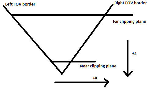
Given the above bullet points, a reasonable top down diagram of our camera will look like this:
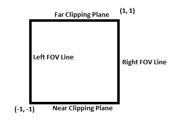
And our projection matrix will transform these coordinates into the following square:
If you are familliar with matrices, you may wonder how this transformation is possible by only multiplying a single matrix. This transformation is different than any of the other types of transformations because it cannot be done as a normal linear equation and therefore cannot be done with a normal matrix multiplication! The key is the 4th dimension (w value) and this is the precise reason we have been working with 4 dimensional matrices and vectors this whole time. By itself the w value does not get us any new transformational capabilities, but consider if we added the following rule before rendering: The vector must be scaled before rasterizing v' = a * v and after scaling, the w value must be equal to 1. Now after some quick algebra (v'.w = a * v.w 1 = a * v.w a = 1/v.w) we know the scaling factor is 1/w. We will use the fact that x, y, and z are multiplied by 1/w to get the desired effect of scaling x and y down as z gets larger.
Scaling the vector by 1/w before rendering will allow us to shrink objects that are further away by more and objects that are closer will appear bigger. If we set w' = -z then as z gets more negative, w' will get higher and our objects will shrink. Why negate the z value? In our diagram above, the camera is pointed along the negative z axis so when a vector has a z value of -10, it should be scaled down 1/10th the size. The equations can be solved for the positive z axis or any axis but in this tutorial I will follow the diagram above. To ensure that each equation can be converted into part of the matrix we have to solve equations of the following form where x' is the x value of the vector in screen space (-1, -1, -1) to (1, 1, 1), x is the value of the input vector in camera space (position relative to the camera) and a, b, c, and d are each values in a row of the matrix and the values we will be solving for.
x' = (a*x + b*y + c*z + d*w) * (1/w')
Since we have already determined that we will set w to -z, we can substitute and get the following:
x' = (a*x + b*y + c*z + d*w) * (-1/z)
To solve for a, b, c, and d for the first row of the matrix, we will use a top down diagram of the camera.
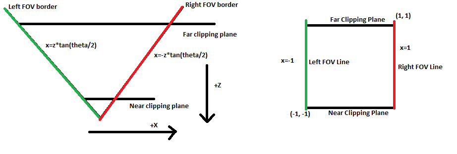
Every point along the field of view lines will be on the far left or right (-1 or 1) edge of our screen. The slope of the line is +/- tan(theta/2) so the equation for the positively sloped line is x = z*tan(theta/2). We want this line to map to the left side of the screen x' = -1so we can plug this into the equations above.
-1 = (a*z*tan(theta/2) + b*y + c*z + d*w) * (-1/z)
Since the x value isnt dependent on the y value, we can set b to 0. It also already has a z term so we can set c to be 0 and there is no need to add a constant since the camera is centered on the x axis so d can be 0 as well. Plugging in these 0 values we get:
-1 = -a*z*tan(theta/2) / z
which simplifies to
a = 1/tan(theta/2)
We can solve the equations for y as well keeping in mind that due to the proportions of the screen, the slope of the y fov lines will the tan(theta/2)*h/w where h is the height of the screen and w is the width in pixels. For the y' row we get the following solution:
b = w/(h*tan(theta/2))
Putting these values in our matrix we get:
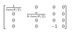
This matrix will work as our projection matrix as-is because we don’t use the z value right now; however in order make a depth map and detect when an object is drawn in front of or behind another, we need to map the z' value to the range -1 to 1 when the z value is in the range between the near and far values. The z value should not depend on the x or y values because the depth does not change as the objects move sideways or up and down. Filling in the known values we get the following equations:
z' = (c*z + d*w) * (-1/z)
Simplified and replacing w with 1:
z' = -c - d/z
We can make two equations out of this, one where the near value is mapped to -1 and one where the far value is mapped to 1. Note that the near and far values are positive distances from the camera but since they will be on the -z axis we will negate them when plugging them in for z.
-1 = -c - d/(-n)
1 = -c - d/(-f)
Solving these equations with basic algebra, we get:
c = (n + f) / (n - f)
d = 2nf/(n - f)
Now our matrix is complete:
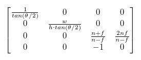
Any vertices in camera space that are multiplied by this matrix will come out in the (-1, -1, -1) - (1, 1, 1) box that we will render in. I put the following function into the Mat4 class to build projection matrices given the parameters assumed above:
static perspective(w, h, near, far, fov) {
	let r = Math.tan(fov / 2);
	let t = r * h / w;
	let v00 = 1 / r;
	let v11 = 1 / t;
	let v22 = (far + near) / (near - far);
	let v23 = 2 * far * near / (near - far);
	let v32 = -1;

	let m = new Mat4();
	m.vals[0] = v00;
	m.vals[5] = v11;
	m.vals[10] = v22;
	m.vals[11] = v23;
	m.vals[14] = v32;
	return m;
}
We also need to add the divide by w step so we will add a method to do this in the Point4 class:
normalizeW() {
	this.x = this.x / this.w;
	this.y = this.y / this.w;
	this.z = this.z / this.w;
}
Notice the w value is not divided. This is because it will be necessary to know the amount the vector was scaled down by later.
At the very top of the drawTirangle function, right after p1-p3 are declared, we can normalize each vector:
p1.normalizeW();
p2.normalizeW();
p3.normalizeW();
Now we are ready to try out our perspective matrix. First lets modify the previous example to make the square move toward and away from the camera. To simplify things the scale is a constant and the square remains centered.
let val = 0;
let buffer = new Buffer(ctx, width, height);
let perspective = Mat4.perspective(width, height, .1, 1000, Math.PI / 2);

let fragShader = (varyings) => {
	return new Fragment(varyings[0], varyings[1], varyings[2], varyings[3]);
}

let vertexShader = (vertex, uniforms) => {
	let newPoint = Point4.fromPoint3(vertex.point, 1);
	newPoint = uniforms.projMatrix.multVec4(uniforms.modelMatrix.multVec4(newPoint));
	console.log(newPoint.w);
	return new Vertex(newPoint, [], vertex.attributes);
}

let v1 = new Vertex(new Point3(-1, -1, 0), [255, 0, 0, 255]);
let v2 = new Vertex(new Point3(1, -1, 0), [0, 255, 0, 255]);
let v3 = new Vertex(new Point3(1, 1, 0), [0, 0, 255, 255]);
let v4 = new Vertex(new Point3(-1, 1, 0), [0, 0, 0, 255]);

let tri1 = new Triangle(v1, v2, v3);
let tri2 = new Triangle(v1, v3, v4);

let square = [tri1, tri2];

function mainLoop() {
	val += .01;

	let zOffs = Math.sin(val*2.5) - 2;

	let translate = Mat4.translate(0, 0, zOffs);
	let scale = Mat4.scale(.3, .3, .3);
	let rotate = Mat4.rotateZ(0);
	let uniforms = {modelMatrix: translate.mult(scale.mult(rotate)), projMatrix: perspective};

	drawTriangles(buffer, square, vertexShader, fragShader, uniforms);

	ctx.putImageData(buffer.imageData, 0, 0);
	buffer.clear();
}

setInterval(mainLoop, 1000/60.0);
This looks like it works, to test it further we can add rotation. To show off our new perspective calculations, we will need to implement a function that lets us rotate around the x and y axis. These functions are very similar to the z rotation function only changing where the values are in the matrix.
static rotateX(r) {
	let m = new Mat4();
	m.vals[0] = 1;
	m.vals[15] = 1;

	m.vals[5] = Math.cos(r);
	m.vals[6] = Math.sin(r);
	m.vals[9] = -Math.sin(r);
	m.vals[10] = Math.cos(r);
	return m;
}

static rotateY(r) {
	let m = new Mat4();
	m.vals[5] = 1;
	m.vals[15] = 1;

	m.vals[0] = Math.cos(r);
	m.vals[2] = Math.sin(r);
	m.vals[8] = -Math.sin(r);
	m.vals[10] = Math.cos(r);
	return m;
}
Now if we replace our rotateZ(0) line with the following
let rotate = Mat4.rotateX(val);
The plane dissapears after it turns around so we can fix this by adding two back face triangles:
let tri1 = new Triangle(v1, v2, v3);
let tri2 = new Triangle(v1, v3, v4);

let tri3 = new Triangle(v2, v1, v3);
let tri4 = new Triangle(v3, v1, v4);

let square = [tri1, tri2, tri3, tri4];
At this point everything should work and look pretty good but if you watch closely, something looks a bit off with the texturing. To explore what might be going on, I overlayed a simple grid texture using the following fragment shader along with 2 new fields in the vertex definitions. The new shader just makes a grid pattern and “rotates” the color that is returned in alternating grid squares.
let fragShader = (varyings) => {
	let r = varyings[0];
	let g = varyings[1];
	let b = varyings[2];
	let a = varyings[3];
	let u = varyings[4];
	let v = varyings[5];

	if ((Math.floor(u * 10) + Math.floor(v * 10)) % 2 == 0) {
		return new Fragment(g, b, r, a);
	} else {
		return new Fragment(r, g, b, a);
	}
}
let v1 = new Vertex(new Point3(-1, -1, 0), [255, 0, 0, 255, 0, 0]);
let v2 = new Vertex(new Point3(1, -1, 0), [0, 255, 0, 255, 1, 0]);
let v3 = new Vertex(new Point3(1, 1, 0), [0, 0, 255, 255, 1, 1]);
let v4 = new Vertex(new Point3(-1, 1, 0), [0, 0, 0, 255, 0, 1]);
After implementing the above code, your output should look something like this:
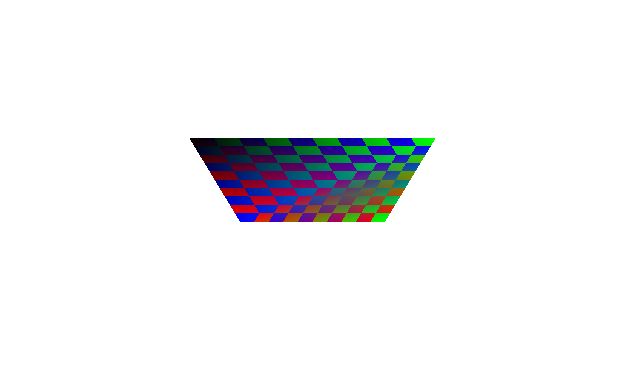
Now it is more obvious there is a problem and that the problem has to do with how we are texturing the triangles. The texture appears to skew down the diagonal line in the middle of the square. It turns out the problem lies in our assumption that we can linearly interpolate values between coordinates. When coordinates are at different z depths this assumption breaks down. The trick to solving this is to divide the values by z before interpolating, then interpolate 1/z as well as the values. To get the correct value back, you just divide by the interpolated 1/z value. This can be proven algebraically to be the correct solution but I will not go over the solution here. Instead I will show the “Interpolate then divide” version which is conceptually correct but impractical to implement and then I will show the “1/z trick” version. I will leave it as an exercise for those interested to prove that these are equivalent.
Definitions of variables used:
v - the interpolated value
x - x position in screen space
a - value between 0 and 1 determining where we interpolate as a percentage between the two values

s - starting value of the left vertex
e - ending value of the right vertex

l - x position of the left vertex in screen space
r - x position of the right vertex in screen space

q - left vertex z value
t - right vertex z value
This set of equations describes the value as it is interpolated in camera space. Notice v is interpolated linearly in camera space between s and e (start and end values). The x position on the screen is interpolated by converting the r and l values from screen space into camera space before interpolating and then dividing by the interpolated z value.
v = ea + s(1-a)
x = (tra + ql(l-a)) / (ta + q*(1-a))
The following equations demonstrate interpolation using the 1/z trick. x is interpolated between r and l in screen space, but v is interpolated by first dividing the start and end values by z, then interpolating, then dividing by the interpolated value (1/z). With a bit of algebra this can be shown to be equivalent to the equations above.
v = (e*a/t + s*(1-a)/q) / (a/t + (1-a)/q)
x = ra + l(1-a)
Since w is our z value after the perspective matrix, we will be dividing by w instead. Negating z in the equations above does not affect the result so we do not have to account for that. To implement the equations, we need to divide all of our varying parameters by w before interpolating. In order to interpolate 1/w, we need to add 1/w as a varying parameter as well. The function I wrote to fix the varyings for all vertices of a triangle is written below.
function perspectiveCorrectTriangleVarying(t) {
	let v1 = t.p1.varyingArray;
	let v2 = t.p2.varyingArray;
	let v3 = t.p3.varyingArray;

	for (let i = 0; i < v1.length; i++) {
		v1[i] /= t.p1.point.w;
		v2[i] /= t.p2.point.w;
		v3[i] /= t.p3.point.w;
	}
	v1.push(1/t.p1.point.w);
	v2.push(1/t.p2.point.w);
	v3.push(1/t.p3.point.w);
}
Now we just need to call this function right before we calculate the varying slopes in the drawTriangle function:
perspectiveCorrectTriangleVarying(triangle);
let varyingSlopes = calculateVaryingSlope(triangle);
Since the varying values have been divided by w, they won’t be correct until we divide them by 1/w again. I created a helper function to use in fragment shaders that calculates the real value of the varying by dividing it by the interpolated 1/w value at the end of the array.
export function getVarying(base, idx) {
	return base[idx] / base[base.length - 1];
}
To get the value of a varying in the fragment shader, you just have to call the getVarying function with the index of the value to retrieve. To test our new perspective corrected varyings, we need to modify our fragment shader to use the getVarying function:
let fragShader = (varyings) => {
	let r = getVarying(varyings, 0);
	let g = getVarying(varyings, 1);
	let b = getVarying(varyings, 2);
	let a = getVarying(varyings, 3);
	let u = getVarying(varyings, 4);
	let v = getVarying(varyings, 5);

	if ((Math.floor(u * 10) + Math.floor(v * 10)) % 2 == 0) {
		return new Fragment(g, b, r, a);
	} else {
		return new Fragment(r, g, b, a);
	}
}
Now that we are modifying the varying array that is passed to the renderer, we also need to clone it in the vertex shader so we don’t modify the values permenantly for the next frame.
return new Vertex(newPoint, [], vertex.attributes.slice());
The distortion seen before should now be gone!